The smaller the details the camera is able to read, the higher the resolution. It is important to understand that the quantity of the matrix pixels is only partially related to the actual camera resolution. This is because of the optics, which is often a bottleneck in the modern digital photo technique. One of the oldest methods to assess resolution is shooting of black and white lines. The quantity of discernable lines you can shoot tells you the resolution. This might sound simple and logical but the problem is whether or not the lines are discernable. Discerning the lines depends on the observer and his visual ability.
Look at Fig.1. You might be able to see thousand of lines per frame because you can definitely see all the lines above the number 10. Perhaps you can see 1200 or even 1600 lines per frame because you can see something above the numbers 12 and 16. Because different people would answer this differently or view the lines slightly differently, if we see the kind of statement "resolution 1600 lines per frame height" this would not deserve special attention.

Fig. 1
Modulation (contrast) transfer function or spatial frequency response gives an idea of a deeper and more objective conception about resolution. Modulation (contrast) is defined in the following way
Modulation (contrast) = (Imax - Imin) / (Imax + Imin) ;
Where Imax and Imin are maximal and minimal intensity.
Let's imagine a series of images, taken by one camera. In the first image there is one black line, in the second there are two, in the third there are six and so on. The lines, beginning from their certain amount in the image, start merging, and eventually will merge to a full extent, reaching the zero contrast:

Fig. 2
Thus, the dependence of contrast from spatial frequency of the lines is obvious. It is that dependence, which is modulation transfer function, that slowly falls from one to zero by increasing spatial frequency. To simplify things, we will measure spatial frequency by cycles per pixel, taking one dark and one light line as a cycle. For instance, in the fragment with 30 lines (Fig. 2) the spatial frequency will equal to 0.25 cycles per pixel then we divide 30 by 120 (fragment length in pixels).
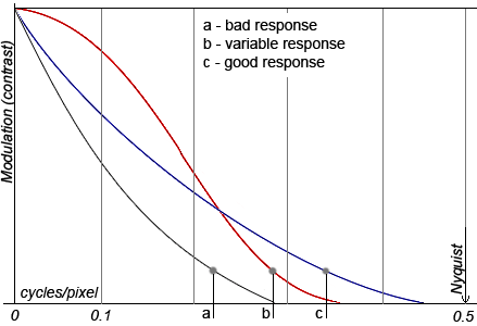
In order to connect MTF with the usual resolution, described in the previous paragraph, it is possible to consider that the lines "are still discerned" with the contrast value in 0.15. Nevertheless, let's note that MTF provides more information about the resolution, than simply the amount of the lines. (Fig. 3)

Fig. 3
Three examples of the spatial frequency response are shown in the picture. In case a the response is weak, the contrast quickly falls by increasing the frequency. In case b, the contrast is well reproduced for small frequencies but worse than in the case c for high frequencies. Hereby, when we measured the resolution with the method, described in the first paragraph, the best result would rather be in case c.
The Nyquist frequency always corresponds to 0.5 cycles per pixel (two pixels per one white and one black line). Obviously it is the frequency, higher of which it is useless to consider the response.
The spatial frequency by the contrast 0.5 is individually singled out and this value is called MTF50. As an example, in Fig. 3, in case a, MTF50 is approximately 0.1 cycles per pixel. Moreover, let's note once more that response MTF50 in case c in the picture is worse than in case b.
There are some methods to model MTF, one of them is based on the analysis of slanted-edge picture. This methodology is described by standard ISO 12233 and is used, according to this standard, in the Quick MTF application. This approach, unlike the rest ones, requires minimal arrangements, and is based on the analysis of images, or more often on their fragments, similar to Fig. 4. It means that it is not necessary to take the lines for modeling. The analysis of transfer from dark part to light one may also provide sufficient information about resolution, and about more besides.


Fig. 4
And now some words about the method itself, if you are interested. The measurement is held by three stages:
See the Basic steps in calculating the MTF for more details.
Sometimes by analyzing edge spread function due to typical "humps" near the edge borders, we can assess the level of sharpening applied to the image. Sharpening is a totality of bitmapped algorithms, directed to the increase of image sharpness. The usage of these algorithms to the analyzing image largely misrepresents the results for measurement of resolution.
Oleg Kurtsev, PhD (okurtsev@quickmtf.com) © 2008